PRL: Circuit Design
As part of the Pneumatic Rocket Launcher project I needed to design a small circuit that would trigger the sprinkler solenoid which opens the valve for a launch. This solenoid is labeled as 24V ( and apparently that rating is for an AC voltage ) but my internet research and careless experimenting has shown it to work with 12V DC. We've been doing test launches with a 3S lipo battery and a button - but this isn't ideal for several reasons.
OK so I need 12V from somewhere? I really don't want to add a 12V battery to this project since nothing else needs that voltage and it is really only needed for a split second...
I've been learning about capacitors and solar circuits in parallel and this seemed like a fine time to combine them. I knew that I could club together whatever charging voltage I needed from individual solar cells and the storage capacity from arrays of capacitors, neither or which was a very complex calculation:
- Solar cells: 3 x 5V in series. Theoretically this is 15V but in reality I tested it above 17V in direct sunlight. After a forward voltage drop of 1.5V through a blocking diode this means around 13-15V should reach the capacitor bank.
- Capacitors: 6 x 2.7V 3.3F in series ( 16.2V 19.8F ). I treat this like a really small battery. Really this should probably be 7 capacitors because the max input from the solar panels is getting uncomforably close to our max capacity. I've read that to be conservative I should assume 50% of what is stated to give plenty of buffer. In my situation it wouldn't otherwise affect the circuit to just add more buffer in this capacitor bank.
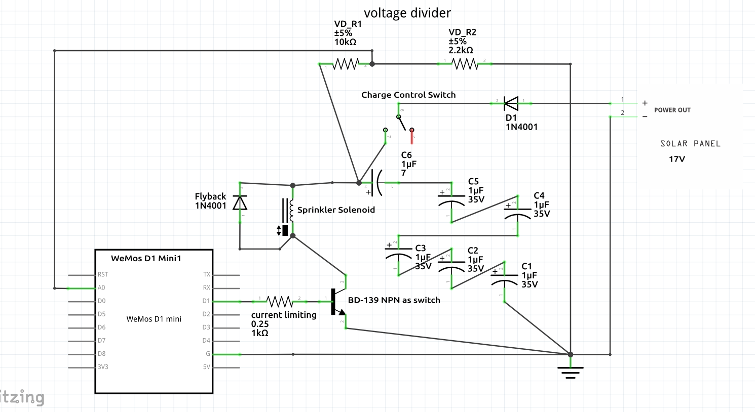
So, we'll temporarily borrow some energy from the sun to launch our rocket. Here is the circuit in it's absolute simplest form. This was novel for me because I actually only did this one in the computer:
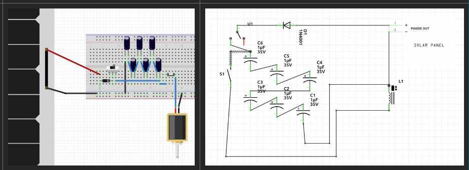
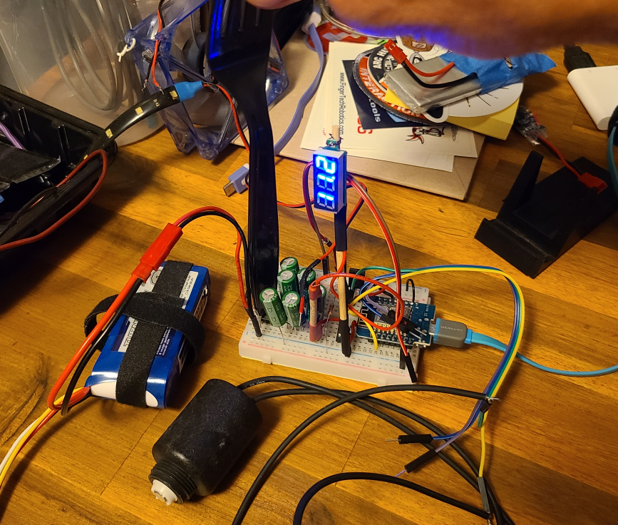
Then I couldn't help myself and had to start prototyping it. Here a 3S lipo, about 12.4V, stands in for the solar panel. I briefly debated relay vs transistor as the switch - decided on transistor because I thought it might be more enlightening.
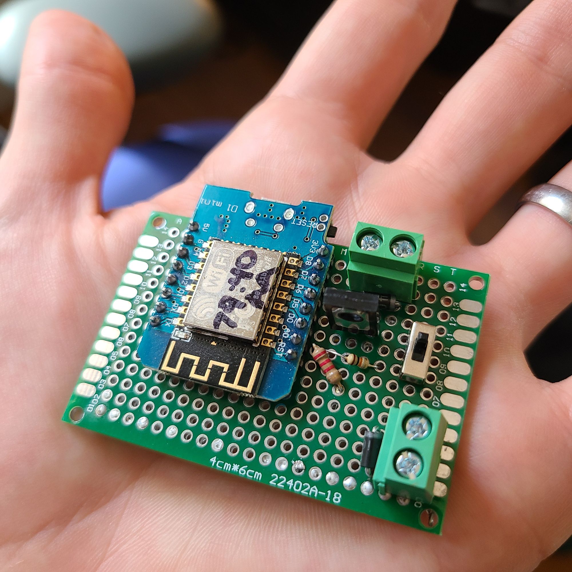
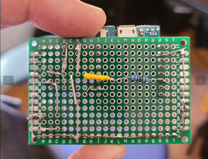
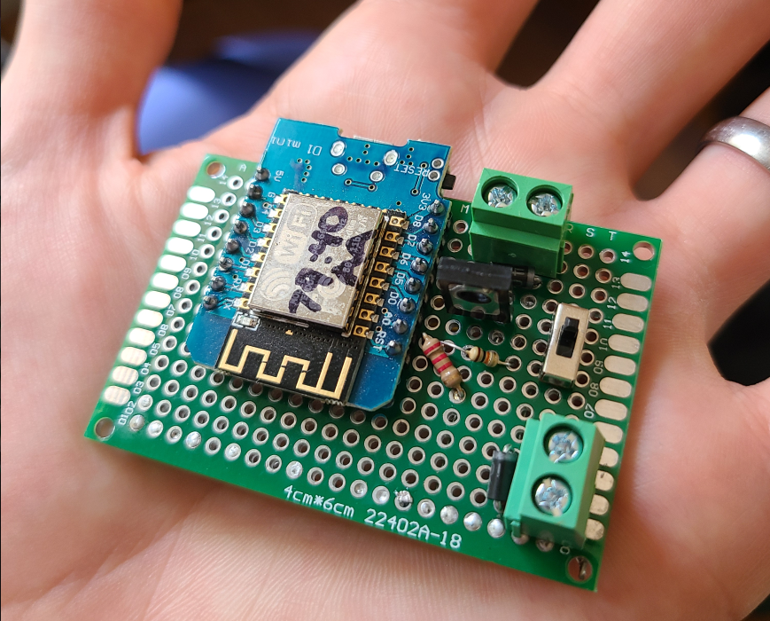
Once it all works there is this hesitation to ever disassemble it. I have prototypes that have been sitting around for years. I mean, what if it never works again and I just can't remember how I had it wired? I told myself that I should be confident in the schematics, but I also took some reference pictures like the one below ( hoping that I would not need them ).
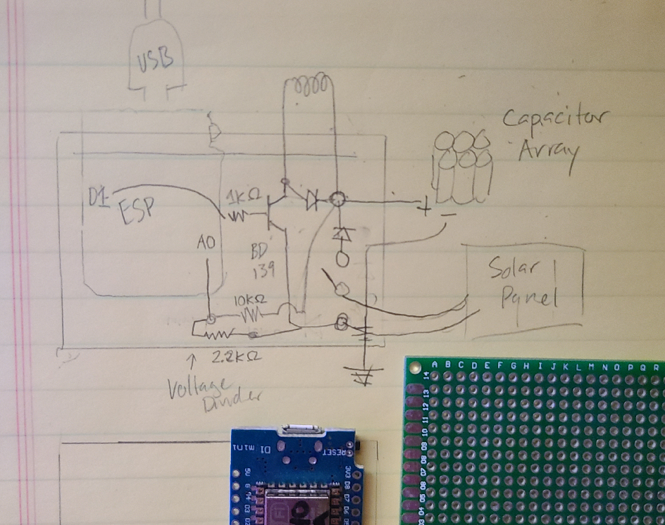
The final schematic helped me 'unfold' the circuit a bit and it started to get easier to visualize how it could be laid out.
I even traced some components onto paper so I could see their relative sizes and experiment with orientations.
Finally I was brave enough to use the 'PCB' tab in Fritzing, which is surprisingly satisfying when you know what you're building. It really forces you to think about making the circuit 2 dimensional.
There are an unlimited number of ways to layout the components, but I:
- tried to minimize crossovers
- tried to give myself space to work - both when soldering and when interacting with the circuit later
- used connectors wherever I thought they would be convenient or make this more modular: The solar panel and load connections.
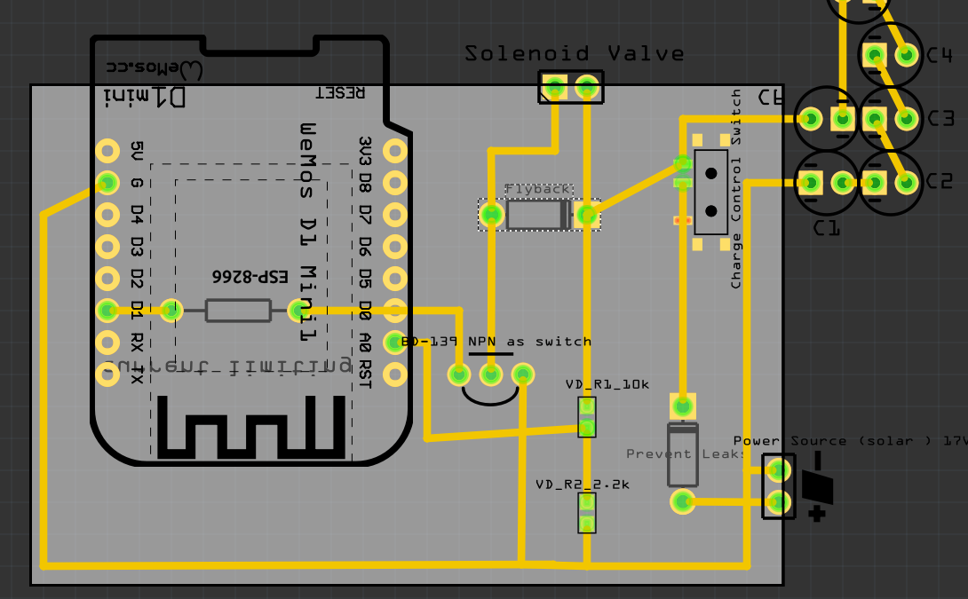
Part of the fun ( and complexity ) is deciding what will happen behind the scenes vs what will be seen on the surface of the perfboard. I generally put components on the front and the bulk of the connections on the back.
There was only one small wiring issue introduced in the transition to the perfboard: The body of the little metal switch was creating a short in the charging circuit, effectively making it not a switch at all. The multimeter helped sort that out pretty quickly and then I destroyed two more switches figuring out how re-solder it correctly.
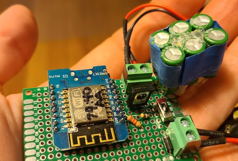
Now the solar panel can actually be switched off from charging the capacitor bank. Here is what it looks like with the capacitor bank assembled and attached:
I have a lot more to learn about Fritzing, but it was great to get to spend this time learning more about schematics and PCB layout. Maybe in the future I'll actually design a PCB and have it manufactured? It is much easier to imagine that now.
A few other lessons learned that should not be forgotten:
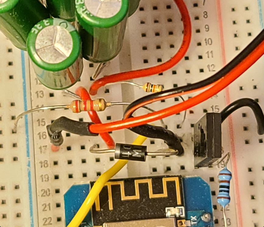
- You definitely need a current-limiting resistor between the GPIO pin and the base of the transistor. I'm still learning how humbling transistors can be, even when you're just trying to use one as a switch like in this circuit. I *think this resistor prevents the voltage supplied by the GPIO from immediately dropping, ensuring a sufficient base-emitter junction voltage (Vbe)
- You have to use a transistor as a switch like this on the ground leg of the load circuit. This is called "low-side switching". I don't know why it is necessary but connecting the load any other way doesn't work for the transistor.
- This circuit warrants using a flyback diode because the load is a solenoid. I fried a transistor ( which took quite awhile to figure out ), I believe because I didn't have this diode in place. I just built the flyback diode in so it's there whether the load is inductive or not.