This is so far the smallest wifi-connected thing I've programmed. Looking back more than 2 years now, this post will document my 'first contact' with the ESP family of hardware. I have since come a long way, but these first few encounters were what got me started.
By definition, the ESP8266 is, "a low-cost Wi-Fi chip with full TCP/IP stack and MCU (Micro Controller Unit)".
I think of it as a really small micro controller with a wifi antenna. It can serve as the wifi connection for a larger microcontroller, or it can run it's own custom firmware and operate like a really micro microcontroller. ( It has limited I/O pins and flash memory ).
Why the -01?
I know that there are other versions of this board available with all kinds of nice features, including:
- On board USB / UART port for flashing code
- Reset button
- larger flash memory ( more than 512k )
- form-factor that fits into a prototyping breadboard
- pin exposed allowing self-wake from deep sleep
- pre-flashed with NodeMCU, etc
The -01 has none of these, so it is the cheapest footprint you can buy. I figured that I would probably fry a few learning how to use them, so I picked up 4 for $9 on Amazon. I feel like it can't hurt to learn the standard chip first.
Basically I'm doing the opposite of what wikipedia recommends:
Novice ESP-8266 developers are encouraged to consider larger ESP8266 Wi-Fi development boards like the NodeMCU which includes the USB-to-UART bridge and a Micro-USB connector coupled with a 3.3 Volt power regulator already built into the board. When project development is complete, you may not need these components and can consider using these cheaper ESP-xx modules as a lower power, smaller footprint option for your production runs.
Note: That advice about using an external 3.3V power supply is critical. The USB-to-UART bridge can't provide the power. Save yourself the hours of frustration and provide a source of power === USB power will not do it.
The Scope of this Article
This article will cover connecting the chip to a USB-to-UART converter and testing out the pre-installed AT firmware. Future articles in this series will cover other firmwares / toolchains for developing on the ESP8266.
In other words, there are much better ways to utilize this thing. I'll cover PlatformIO in a later post :)
'Enabling' the chip
Do you want your chip enabled?
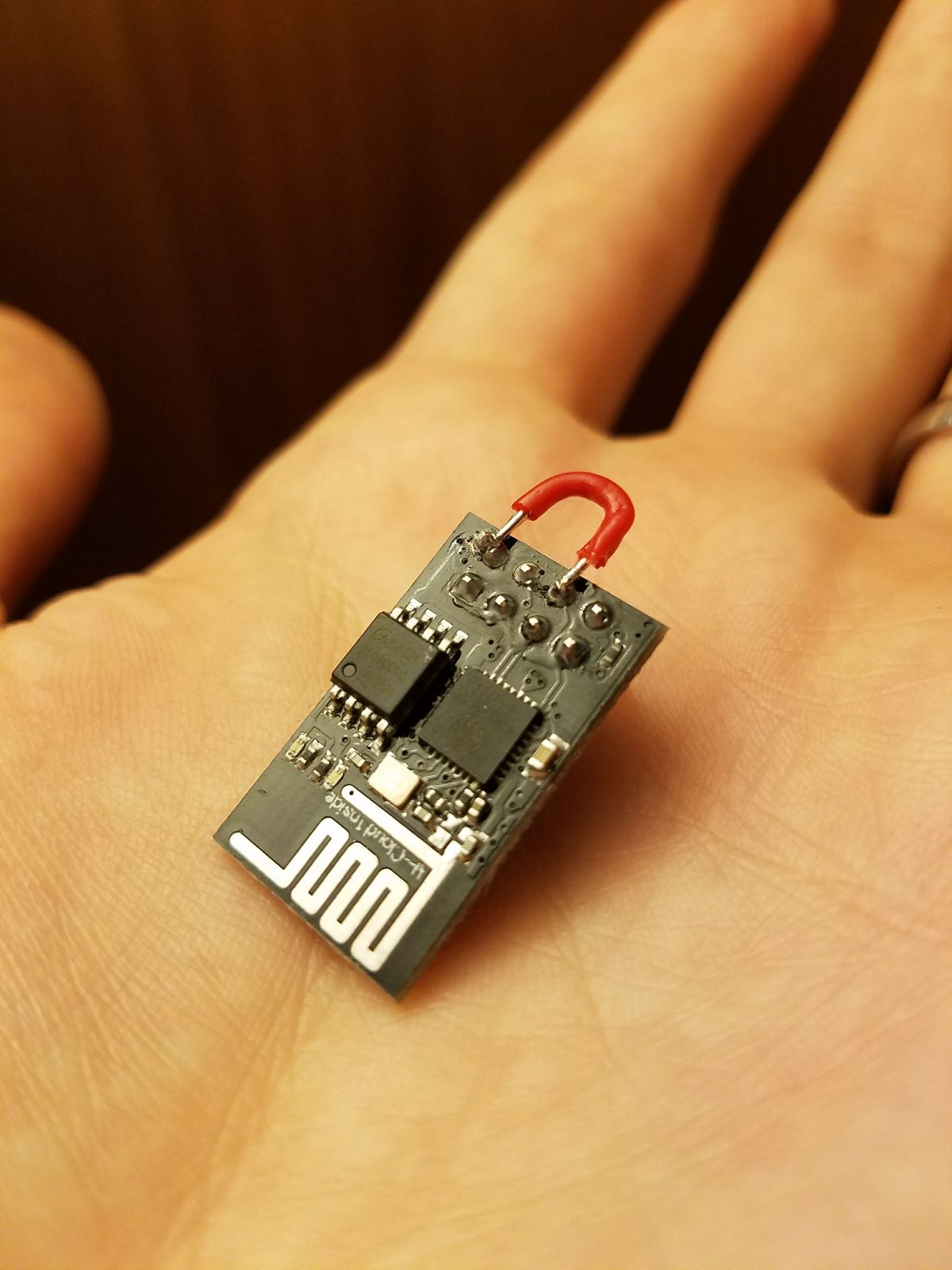
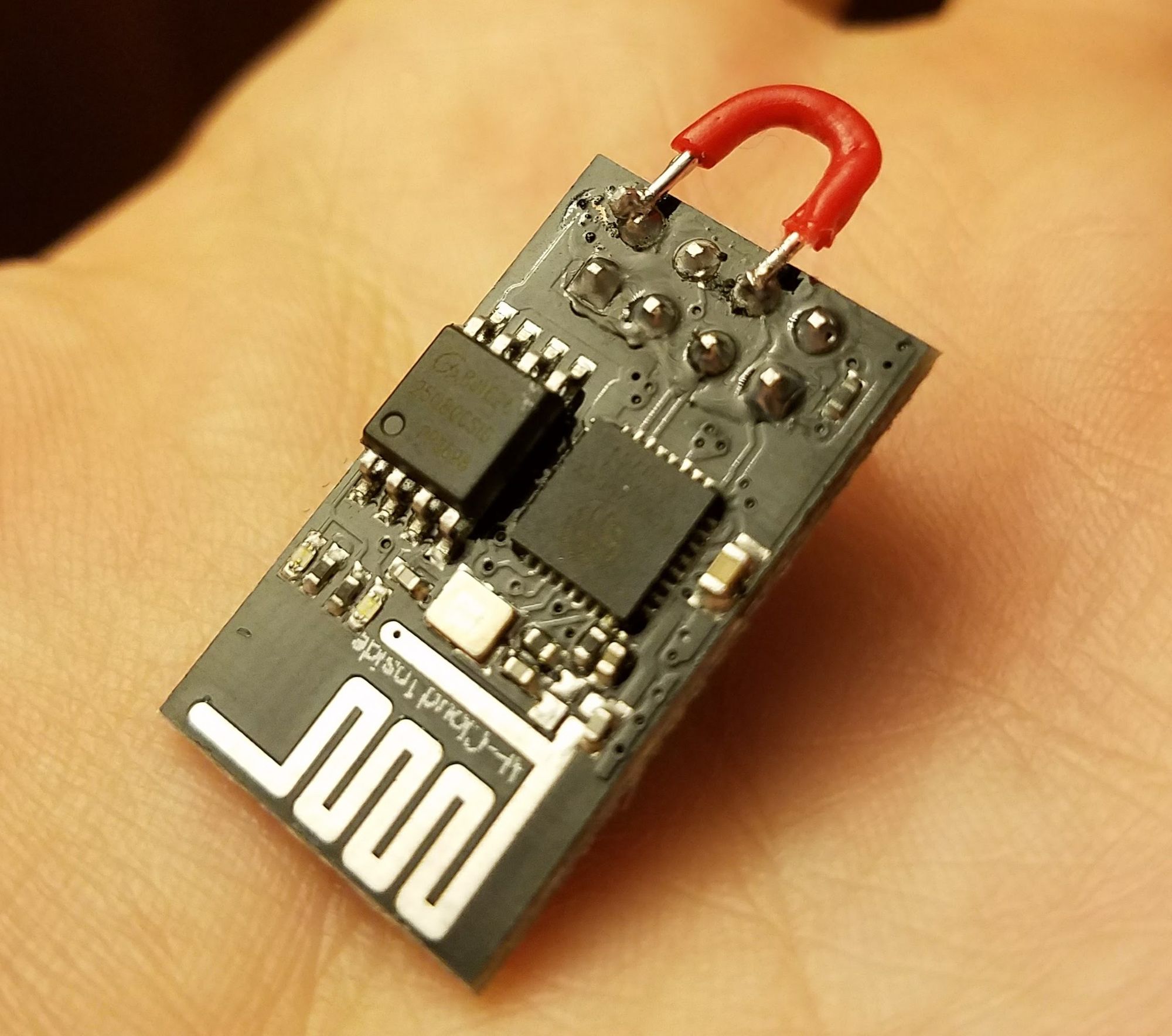
Yes, you do. The CH_PD pin has to be connected to the VCC/3.3v pin in order for the chip to be 'enabled'. I could see this being easy to forget, and therefore frustrating. I soldered a jumper across the pins to avoid making this mistake ( see above picture ), at least until I build a programming rig.
AT
The chips I bought came pre-loaded with the default firmware, which I believe is created by the manufacturer, Expressif. The stock firmware is referred to as AT, and works by issuing serial commands to the chip. This is often suggested as a first exercise with one of these chips, and confirms that it arrived in working condition.
I was able to run this test with a basic CP2012 USB-to-UART thing connected to my laptop. The connections are pretty straightforward. Remember to use 3.3v supply voltage and signal levels. ( In this case I didn't have any issue powering the chip directly from the CP2012 ) TX to RX, RX to TX:
In order to issue serial commands and view serial responses, you can use the terminal of your choice. Arduino IDE might be your easiest option if you prefer something like putty or RealTerm.
Using an overview of AT commands, I was able to pull off most of the basic stuff:
Show firmware version
AT+GMR
AT version:0.25.0.0(Jun 5 2015 16:27:16)
SDK version:1.1.1
Ai-Thinker Technology Co. Ltd.
Jun 5 2015 23:07:20
List Access Points
AT+CWMODE=1 // explicly set CWMODE to 'client' so CWLAP will work
OK
AT+CWLAP // list access points
+CWLAP:(4,"ATT728",-90,"38:3b:c8:75:83:ca",1)
+CWLAP:(4,"GGP",-89,"b8:a3:86:14:d1:10",1)
+CWLAP:(4,"GGP_almond",-78,"e4:71:85:02:a5:30",2)
...
Joining an Access Point
AT+CWJAP="your_network","pa$$word"
WIFI CONNECTED
WIFI GOT IP
Info about client connection
AT+CIFSR
+CIFSR:STAIP,"192.168.2.8"
+CIFSR:STAMAC,"18:fe:34:99:d5:83"
Info about the joined access point / are we joined to an AP ?
AT+CWJAP?
+CWJAP:"cholenet","ac:9e:17:7f:37:60",6,-60
Disconnect from an AP
AT+CWQAP
Conclusion
OK, so this is cool. For having done nothing but connect the wires, this is something. Its kind of flaky though. I would say that my commands actually succeeded about 60% of the time. It seems clunky to attach one of these to another MCU and have to do all WIFI commands via serial commands.
So of course there are larger ( more $ ) boards with builtin wifi chips, but I think I'm actually going to go the other direction and learn how to program all of my logic into the ESP-01 itself.
The next article in this series will cover the build and use of a 'flashing jig', which will allow me to flash my own custom firmware ( avoiding the whole AT thing )
This article discusses my first contact with the ESP family of chips, of which there are many. I hope that I find the time to continue this series and share more of what I've learned. ( deep sleep / power consumption / solar powering, AMQP )
UPDATE:
The more that I learn about microcontrollers and electronics, the wiser the quote from the wikipedia page seems. Every project is about your requirements. If you only need 1 digital I/O pin, then a cheap-ass board like this might be a fit
The footprint/formfactor of these boards ranges widely depending on how much of a 'developlent' board it is considered. A more developer-friendly board will generally have more features, be larger, more expensive, (better documented/discussed), and consume more power. The equivalent of this in the ESP-verse is the "NodeMCU devkit board"
A development board will commonly have:
a convenient power supply ( barrel-jack or USB ) with overvoltage protection
UART & conveniently-exposed serial interface ( often in that same micro-USB port )
analog-to-digital converters, protection circuits
On the flip side is a more 'production'-like board ( this ESP-01 being an example ). It has absolutely none of the niceties. The first and most noticable difference is that without the onboard UART, flashing becomes a much more complex activity. ( see later articles )