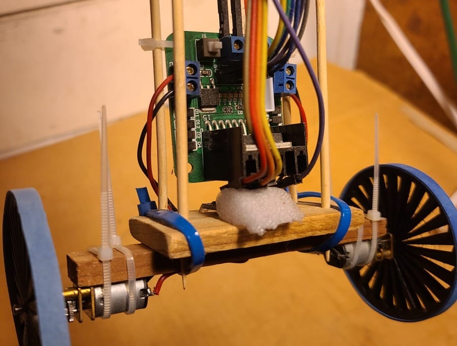
Yes, there was an original balancing robot. I was curious about PID controllers. I lifted some generic balancing robot code for an Arduino and with a little adaptation and some cheap components I was able to build and tune something that would balance. It was adorable but had a lot of shortcomings.
- Using brushed DC motors meant controlling direction with the H-bridge and using PWM to control the speed. It is really hard to do low-speed PWM control, meaning the 'balance' achieved is more like gently oscillating between two unstable states.
- Speed control was affected by battery state of charge since the L298N just passes the voltage through. A PWM signal with a 75% duty cycle will generate a different motor speed at different voltages. There was really no guarantee the motors were turning the same speed at the same voltage and signal value to begin with.
- no wireless/radio for telemetry or remote control
- Looks janky. I made it tall intentionally so the balancing effect would be more dramatic, but the zip ties are a little too garage-core.
| Original | New & Improved | |
| MCU | Arduino Nano | ESP8266 (12-F) |
| IMU | MPU6050 | MPU6050 |
| Motors | Geared, brushed DC motors | NEMA11 stepper motors |
| Motor Drivers | L298N H-bridge | A4988 |
| Voltage | 7.4V (2S / 2-cell-series Lipo) | 12V (a 3S Lipo) |
The New Design
I wanted to design a platform for this that would be open-ended and adaptable for experimentation. I like the aesthetic and material properties of the bamboo skewers, but decided that 3D printing the platforms in PLA would be a big improvement. This time zip ties will be for cable management only and not for holding the motors on.
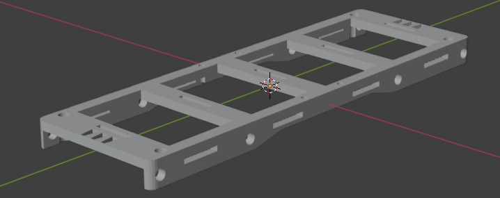
I adapted this NEMA11 bracket design into a platform for two opposing motors using Blender.
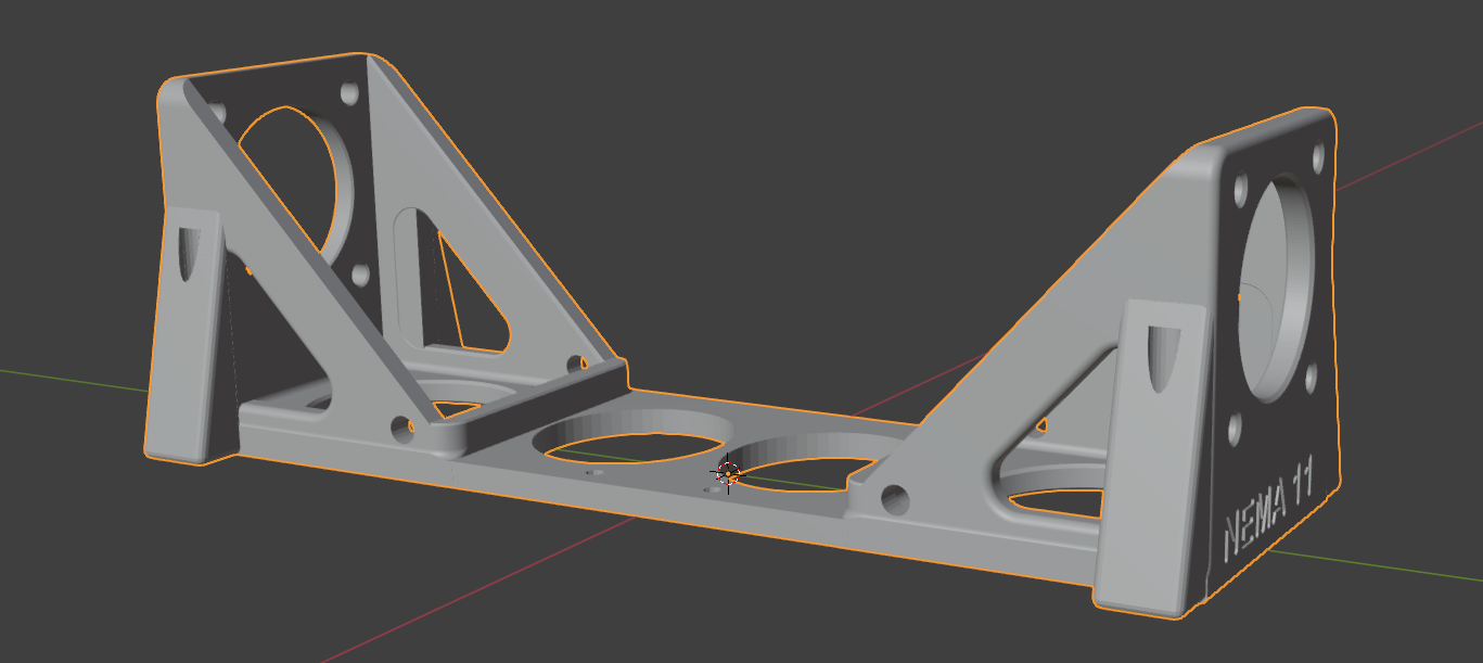
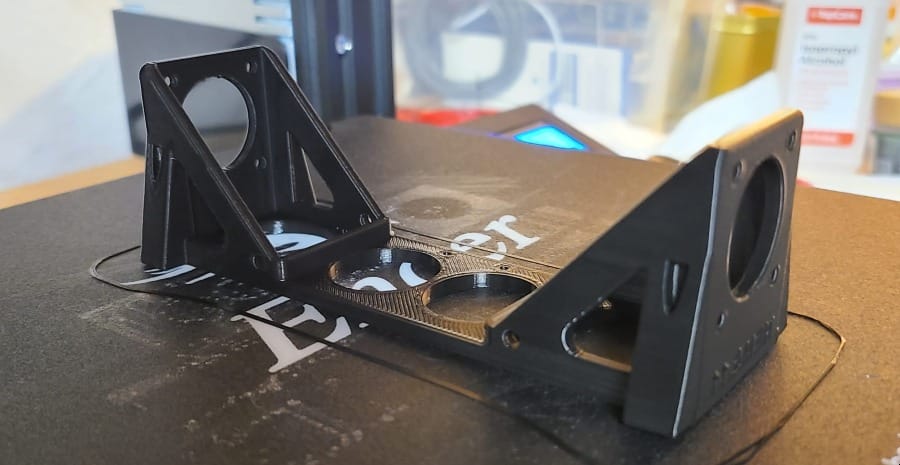
Then these little platforms are designed to friction-fit onto the bamboo uprights. I added extra holes for mounting more sticks laterally and slots for velcro strapping and cable management.
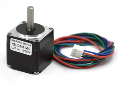
Wheels are one of my favorite things to design since they come out so nice and you can print any motor shaft size/shape necessary. For example, these need a 4mm D-shaft.
The New Build
Having a low center of mass generally makes something more stable. However, and this is weird but true - an inverted pendulum ( the exact opposite of low and stable ) can also be easily balanced if it has a good control system. This is why its easier to balance a long stick vertically on your finger than a short one.
Because I am doing this to learn about control theory, and because it looks funnier and cooler, I'm making it tall again.
Remote Interface
Using the ESP8266 means having most of the same GPIO capabilities of the Arduino but it also has the 2.4Ghz Wifi. I have it hosting a web server and created some simple APIs for updating the PID variables. For the time being I have a locally-hosted web form and logging UI. This allows me to tune the balancing behavior in real-time and get more insight into what is going on internally.
While bench testing it would probably do to just use Postman, but eventually it will run as an access point and host a control / telemetry UI.
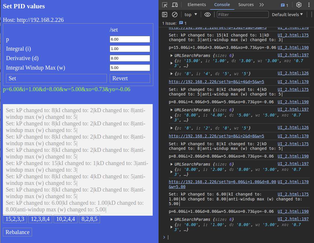
To update the PIDs I POST arguments like p=12.00&i=2.00&d=6.00&w=4.00&xo=1.04&yo=-0.04
I really want full-blown websocket telemetry so I can make an interactive, real-time 3D digital twin with ThreeJS, but... I get distracted so easily. The main thread's main job is to keep things from literally crashing, so piling on extra duties is probably not a good idea. I'm throttling the incoming requests to the server for this exact reason.
Sensor Drift
This whole thing is still just a 1-axis balancing act, so the accuracy of the estimated angle of tilt on the Y axis ( as I have it mounted ) needs to be good.
The MPU6050 is a super cheap IMU and apparently if I wasn't so cheap I would have bought sensors that don't drift as much. However, cheap sensors are often totally satisfactory and the bad carpenter blames his tools, right? Instead this will be an opportunity to learn about compensating for accelerometer drift.
Since an accelerometer measures changes in angular velocity, when it 'drifts' it means that even when it is sitting absolutely still it thinks it is slowly speeding up. This causes the robot to think it should compensate as if the ground was tilting beneath it, when in reality is isn't so ... it becomes a falling robot.
The gyroscope doesn't suffer from drift on the X or Y axes because gravity provides a constant pull on the Z axis. The arc tangent of X and Z is the rotation around the Y axis, which is what I need. This provides a nice stable signal and the gyroscope reading alone can be used to balance, but it has a slower response and just isn't as snappy.
Theoretically, the signals from both sensors should be mixed with a heavier weight on the accelerometer. Mixing doesn't correct the drift problem so I tried to think of a clever way to use the gyroscope's gravity-grounded idea of pitch to correct the drifty accelerometer. I think this is called dynamically calibrating, which feels better than trying to manually calibrate a static 'drift offset' - if I can get it to work.
Drifting Away
There is another source of drift that can't be blamed on the sensor. Originally I thought that if the robot stayed tilted one way a tiny bit that the Integral would pile up in the PID output and nudge it back the other way. What I see happening is the robot start heading one direction, slowly accelerating until the motors just can't keep up. I guess this isn't drift but I don't have a better term for it.
What I haven't taken into consideration yet is the robot's current direction and speed when evaluating what to do next to stay balanced. I need to pass the robot's current speed and direction into the PID controller so it can be factored into the output. The ideal would be, "stay balanced, and don't go anywhere - by keeping your speed down".
To Be Continued...
I feel like this is a reasonable place to conclude since I can claim a few improvements over the original. Obviously there is more to be desired and learned.
To be Done
- incorporate current speed into PID controller
- Solder the prototype circuit onto perfboard
- cable management
To Be Learned:
- better dynamic calibration techniques to deal with accelerometer drift
- better understanding of appropriate max motor speeds at various step sizes
- how to actually measure performance other than just subjective analysis ( "Does it fall over or not?" )
- Explore more control methods like turning ( independent wheel control ) and moving in a specific direction ( falling in a very controlled way )